|
CGM Simulator
0.1.3
A CGM simulator to demonstrate the BLE CGM profile v1.1
|
Bluetooth Low Energy (BLE) emerges as part of the Bluetooth Core Specification V4.0. BLE positions itself as a short range wireless communication protocol that limits power consumption. As part of the power optimization strategy, BLE reduces connection event frequency and packet size.
Packet size reduction becomes possible when both parties in a conversation agree on the same set of rules, including data field, data size, data format ,packet type, behavioral logic etc. These rules are grouped into a unit called service. By implementing the same service on both ends of communication, the overheads to interpret the message are eliminated.
Each service dedicates to an application. For example, the Battery Service defines rules for BLE message carrying the battery information of the device. Whenever BLE expands into new applications, new services are created. The corresponding software needs to be implemented in order to use a new service.
A recently approved BLE service is Continuous Glucose Monitor Service (CGMS). It standardizes the information exchange rules between a collector and a CGM sensor. Specifically, the CGMS describes the packet format for reporting a glucose measurement, device feature, device status, session start time, sensor runtime and history records. Moreover, it specifies data structure for configuring a CGM (eg.set hyperglycemia alert). As data format and behavioral logic are well defined by the specification, the data collector device and the CGM sensor can be developed independently, provided that both of them conform to the BLE CGMS specification. In such way, the interoperability between CGM sensors and collectors device becomes feasible.
This software library is an implementation of the Continuous Glucose Monitor Service (CGMS) on the Texas Instrument (TI) BLE stack. The library implements the semantic definition, data structure, application level behavior of a CGMS. At the same time, the compiled program can be run on TI's CC254X series of BLE chips.
The application specific CGMS implementation in this library is built on top of the more generic BLE protocol layers, including the Generic Attribute (GATT) layer and the Generic Profile Access (GAP) layer. These layers are implemented in the TI's BLE stack library, and generally they remain the same for different services.
Precompiled images are also available here. Manager APP developers may find it handy to flash those images into a TI evaluation module.
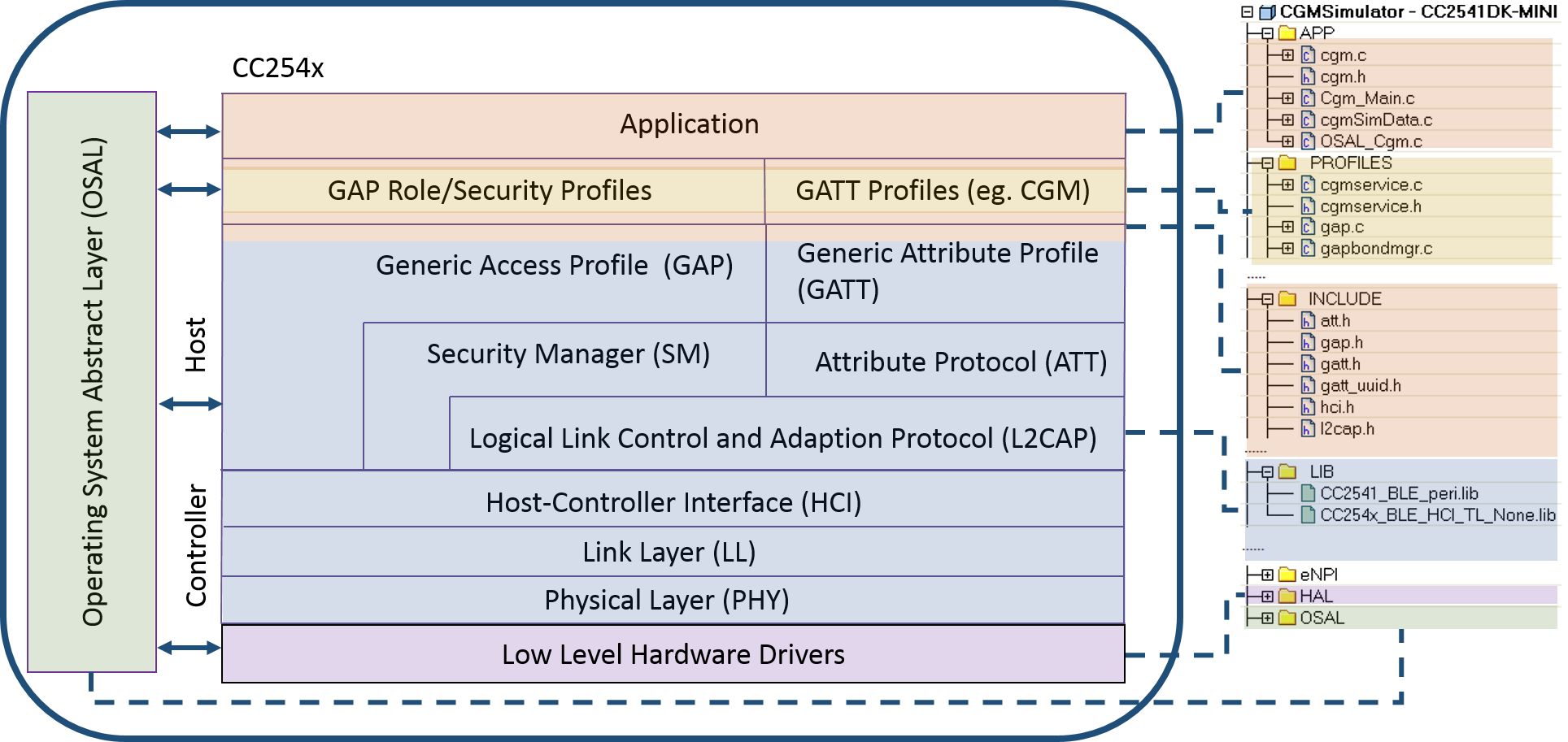
The CGM sensor simulator is implemented on a single chip CC254X from Texas Instrument (TI). Coming with the chip is the TI operation system, TI Bluetooth LE software stack, and Bluetooth LE profiles.
The above diagram shows the one to one mapping of the software source files with the CGM simulator architecture. The file hierarchy on the right will appear in the workplace of the IAR workbench when opening the project file ($PROJECT_DIR/CC254XDB/CGMSimultor.eww).
Starting from the bottom, HAL (Hardware Abstract Layer) implements the drivers for the peripheral modules on the chip and the circuit board. These files are hardware dependent. Here is the official manual for the HAL API.
LIB (CC2541-BLE-peri.lib) implements the Bluetooth LE stack. This library is supplied in a closed source form by TI. The functions inside the library can be called by the upper layers through the exposed APIs defined under INCLUDE (exposed APIs). An official TI BLE stack API manual is host here.
PROFILES configure those services that the current Bluetooth LE device supports. In the CGM simulator, the profile consists of CGM service (cgmservice.c), Bond Management Service (gapbondmgr.c), Battery Service etc. These files define the characteristics to be included in the service. The implementation of service should be in compliant with the BLE service specifications. The current CGM simulator software emphasizes the implementation of the CGM profile.
APP (application layer) folder contains implementation of the behavioral logic behind each of those characteristics defined in the profile. They surround the CGM sensor functions, such as sampling the glucose estimate values, setting the session start time, storing glucose measurement records and later retrieving them via record access control point (RACP).
OSAL (OS abstraction layer) is the quasi-realtime operation system that coordinates micro-controller resource among different layers. Additionally, it provides mechanism to pass information among layers asynchronously. An account for the TI OSAL API can be found here.
Please note that the portion of BLE stack source code and library provided by TI is protected by Texas Instruments Incorporated Software License . In brief, modification or redistribution of the TI code is legitimate only when the code is used with a TI chip. For this reason, the TI licensed code is not host in this repository, user needs to download then here and follow the instructions in Installation Guideline , before the CGMS application can be compiled.
For application layer code ($PROJECT_DIR/Source/), they are created and licensed by the Center for Global eHealth Innovation. The MIT License applies to this portion of the code, which allows the user to modified, redistribute and relicense the software.
In this section, the five fundamental operations of the CGMS are introduced. Please clink onto the related link for detailed information.
Record Access Control Point (RACP)
CGM Specific Operation Control Point (COCP)
Characteristic Read
Characteristic Write
Glucose Measurement Update
In this section, a step by step guide for software installation is presented.
| Components | Description | External Link |
|---|---|---|
| TI CC2541 Mini Development Kit | The hardware platform to load the compile firmware for demonstration. This kit is sufficient in developing BLE embedded software. | Link |
| TI CC2540 Mini Development Kit (Optional) | A similar BLE development hardware kit as CC2541 Mini Development Kit. However, the CC2541 chip has lower power consumption but higher transmission speed. | Link |
| TI BLE Stack | The software kit provided by TI. The stack consists of software libraries for the CC2541MiniDK, including hardware configuration files, a quasi-OS, BLE stack libraries and some application projects. | Link |
| IAR Embedded Workbench for 8051 v8.20.2 | An IDE for embedded software development. It provides the emebedded C code compilation tool chain. This version is recommended because of official support from TI and our CGM service was developped in IAR v8.20.2. Newer version of IAR Embedded Workbench is available from the IAR website, but the project needed to be configured to work with newer version of IAR (Working with IAR Embedded Workbench v8.3 or Newer see here). | Link (v9.1) |
As the project was developed in IAR for 8051 v8.20.2, opening the project with newer IDEs will raise compatibility issues.
First of all, the IDE will prompt to convert the project files into newer versions (figure). Click "yes" to confirm the conversion. The project configuration will be updated to the newer IDE.
The second issue occurs when the project is compiled. The console ouptut an error stating "Error[e16]: Segment ISTACK (size: 0xc0 align: 0) is too long for segment definition. At least 0xe more bytes needed." (figure). To fix the problem, remove the "_NR_OF_VIRTUAL_REGISTERS" from the linker file (i.e."C:\\Texas Instruments\\BLE-CC254x-1.4.0\\Projects\\ble\\common\\cc2540\\ti_51ew_cc2540b.xcl", if the BLE stack files are installed in the default location), the example code is highted in this figure.
Tackling the above two issues should allow code compilation.
Implementing an application level function on the current software generally involves three steps. In the following instructions, the implementation of a set hyperglycemia alert function over the CGM Specific Operation Control Point (COCP) Characteristic will be used as an example. Set hyperglycemia alert registers the alert threshold with the CGM sensor through a write command to COCP value.
Create a pathway from lower GATT request to the application layer callback function.
When the controller writes/reads a value to/from a characteristic, the write/read request will first arrive the CGM_WriteAttrCB / CGM_ReadAttrCBfunctions, respectively. The write/read call back functions relay the request to the application level callback function (cgmservice_cb).
A majority of the processing logic should be done inside the cgmservice_cb function, depending on the input request type and request content. By creating a pathway between the GATT and the app level function, it is required to add in a case for the new command in the callback function and the subsequent processing logic.
In the case of set hyper alert threshold, the write request to COCP exists in the cgmservice_cb as,
switch (event)
    {
    case CGM_CTL_PNT_CMD:
            {
            cgmCtlPntMsg_t* msgPtr;
            msgPtr = (cgmCtlPntMsg_t *)osal_msg_allocate( sizeof(cgmCtlPntMsg_t) );
            if ( msgPtr )
            {
            msgPtr->hdr.event = CTL_PNT_MSG;
            msgPtr->len = len;
            osal_memcpy(msgPtr->data, valueP, len);
            osal_msg_send( cgmTaskId, (uint8 *)msgPtr );
            }
            }
    break;
    }
As we see that the callback sends out an OS message to place a COCP event processing request. As the logic behind COCP command can be potentially large, it is better to leverage the task scheduler of the TI OS to guarantee that time critical tasks have a chance to access the MCU.
Periodically, the function cgm_ProcessOSALMsg will be called by the OS to process pending messages. An excerpt of the function is shown below, and it invokes the cgmProcessingCtlPntMsg to process the message.
static void cgm_ProcessOSALMsg( osal_event_hdr_t *pMsg )
    {
        switch ( pMsg->event )
        {
        case CTL_PNT_MSG:// Receive CGMCP write message from the lower GATT layer
            cgmProcessCtlPntMsg( (cgmCtlPntMsg_t *) pMsg);
            break;
        }
    }
Now the message reaches the cgmProcessCtlPntMsg, which provides logic to process the received COCP command. In the function, a switch statement is present, with each case processes a specific op-code. By adding a case corresponding to the set hyper alert op-code, the pathway between GATT and upper processing app is created.
    switch(opcode)
    {   \/\/Implement the set/get communication interval
        ....
        case  CGM_SPEC_OP_SET_ALERT_HIGH:
        \/\*Application logic for processing the set command goes here\*\/
        break;
        ....
    }
Implement the application level logic.
Starting from cgmProcessCtlPntMsg, the logic is strictly confined within the application layer, which means that it is written into the cgm.c file. In the example of setting hyper alert threshold, the implementation can be as follows,
    switch(opcode)
    {
        ....
        case  CGM_SPEC_OP_SET_ALERT_HYPER:
        \/\/Get the input value
        operand=pMsg->data+1;
        operand_len=pMsg->len-1;
        \/\/Set the local variable
        cgmHyperThreshold=BUILD_UINT16(operand[0],operand[1]);
        \/\/Prepare the response message
        ropcode=CGM_SPEC_OP_RESP_CODE;
        roperand[0]=opcode;
        roperand[1]=CGM_SPEC_OP_RESP_SUCCESS;
        roperand_len=2;
        break;
        ....
    }
In the above code segment, the operand within the COCP write request is extracted. Afterwards, the local variable storing hyperglycemia alert threshold is set with the input value. There are associated logic added in the glucose reporting function, which sets the hyperglycemia alert flag when the most current glucose estimate exceeds the threshold; but it is trivial and outside the scope of this instruction.
It worths mentioning that the above code is for demonstration purpose, it is not yet perfect. A possible improvement is testing the input threshold value before storing it into a local variable. The details are up to the implementation of the glucose monitor.
Feeding the process result back to GATT layer
After the internal variable is updated with the input threshold value associated with the COCP command, collector needs to be informed about the operation result, as required by the CGMS specification. The method of result feedback needs to be an indication to the COCP characteristic.
In the last few lines of the previous code segment, the operation result report is being prepared. Response op-code is being set, and the response operand is loaded with a result value.
Lastly, the prepared response is fed into a function called cgmCtlPntResponse.
static void cgmCtlPntResponse(uint8 opcode, uint8 * roperand, uint8 roperand_len)
{
    cgmCtlPntRsp.value[0]=opcode;
    cgmCtlPntRsp.len=1+roperand_len;
    osal_memcpy(cgmCtlPntRsp.value+1,roperand, roperand_len);
    CGM_CtlPntIndicate(gapConnHandle, &cgmCtlPntRsp, cgmTaskId);
}
The cgmCtlPntResponse sends out an indication to the COCP characteristic through the GATT layer.
Up to this point, the 3-step procedure of adding an application function has been walked through. Other functions can be implemented in a similar manner.
The above is a simplified version of the development process should help potential developers get up to speed quickly. For a deeper understanding on software development on CC254x, the following document are recomended,
Once the source codes are compiled into .hex files. It can be flashed to a target hardware platform using TI SmartRF Flash Programmer. The following diagram illustrates the steps involved in flashing a hex images to the hardware.
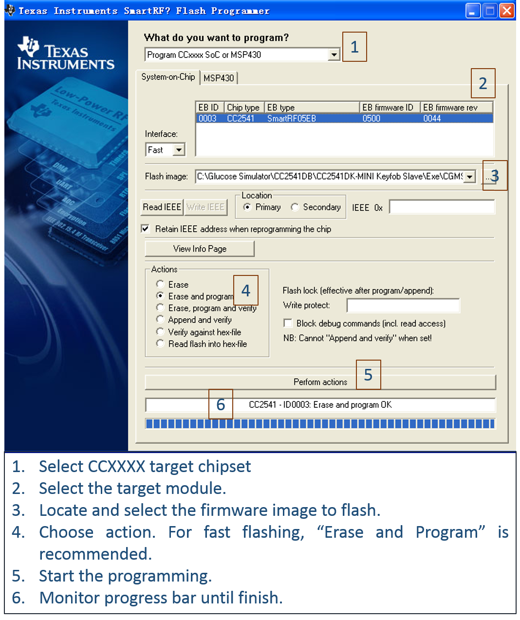
APP developers, who need a CGM simulator agent to quickly test out a collector implementation, may find it handy to flash the precompiled images to a CC2541 evaluation module. These images locate in /Image/CC2541. Different subversions of the agent offer different levels of capability, which are summarized in the followint table. User can select and flash the image based on individual needs.
| Version Number | CRC-Checking | Pairing Required | Session Autostart | Additional Functions1 | Remarks |
|---|---|---|---|---|---|
| v0.1.3a | Most basic implementation. It does not require pairing and CRC checking. Mainly for testing purpose. To start reporting glucose, send a "0x1A" to CGMCP. | ||||
| v0.1.3b | * | Most basic implementation. It does not require pairing and CRC checking. Mainly for testing purpose. | |||
| v0.1.3c | * | Require pairing for read and right characteristic. PIN:19655 | |||
| v0.1.3d | * | * | Compliant to the standard in terms of security mode and integrity check. This version passes a majority of PTS tests2 . PIN:19655 | ||
| v0.1.3e | * | * | * | Compliant to the standard in terms of security mode and integrity check. This version passes a majority of PTS tests2. PIN:19655 | |
| v0.1.3f | * | * | * | * | Compliant to the standard in terms of security mode and integrity check. This version passes a majority of PTS tests2. Auto-starting the measurement.PIN:19655 |
| v0.1.3g | * | * | Full functionality and autostart a glucose reporting session. It does not require pairing and CRC checking. Mainly for testing purpose. |
1They include optional functions such as calibration, patient define high/low level alert, etc.
2This version passes all the mandatory PTS test cases given that prerequisit conditions are met (a certain number of records are stored in the data base etc.). Subjecting the image to test will only pass a majority of PTS test cases.
 1.8.6
1.8.6 
